ESP8266EX offers a complete and self-contained Wi-Fi networking solution; it can be used to host the application or to offload Wi-Fi networking functions from another application processor. When ESP8266EX hosts the application, it boots up directly from an external flash. In has integrated cache to improve the performance of the system in such applications.
NodeMCU ESP-12E dev board can be connected to 5Vusing micro USB connector or Vin pin available on board.
The I/O pins of ESP8266 communicate or input/output max 3.3V only. i.e. the pins are NOT 5V tolerant inputs.
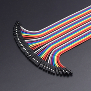
In case you have to interface with 5V I/O pins, you need to use level conversion system (either built yourself using resistor voltage divider or using ready to use level converters
STEP- 1 Installing Arduino Core for NodeMCU ESP-12E Using Arduino Boards Manager
As shown in the image, Copy the .json link with latest stable release of NodeMCU package from Github page here.
Step 2: Insert Link for .json NodeMCU Package Files into Arduino IDE
Paste the copied link and insert it in Arduino IDE using following sequence-
File –> menu –> Preferences
Paste copied link into the area shown in black box in above image.
Close and restart the Arduino IDE.
Step 4: Tools – Boards Manager
Tools –> Boards manager and search for ESP8266 and install the libraries/files given under heading ESP8266 by ESP community.
Restart the Arduino IDE once again.
Step 4: Selecting NodeMCU Board in Arduino IDE
Go to Tools –> Boards (scroll down the list of boards) –> Select NodeMCU 1.0 ( ESP-12EModule).
Select the Port number at which you have connected nodeMCU. Rest of the settings can be left to default values.
CIRCUIT DESCRIPTION
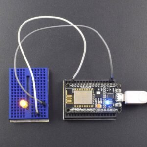
We will be connecting external LED directly to GPIO16 or D0 pin of NodeMCU (no need of external current limiting resistor). This is the pin number for onboard LED or BUILTIN_LED
LIBRARY REQUIRED
OUTPUT
Go to File –> Examples –> ESP8266 à Blink
Upload the sketch to ESP and the On-board LED blue and external LED red starts blinking alternately at every second.
Note- In case, if Arduino IDE version 1.6.7 fails to work for you, try to go back to arduino 1.6.5 or backwards. (some NodeMCU boards have issues with latest versions of Arduino IDEs and going to earlier versions of Arduino IDE solves the problems).
Reviews
There are no reviews yet.
Be the first to review “Control LED by programming NODE MCU ESP8266-12E sing Arduino IDE”Cancel Reply


")

Reviews
There are no reviews yet.